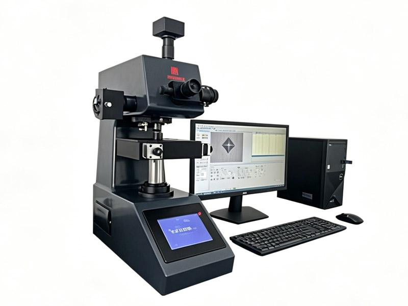


(The image is for reference only; please refer to the actual product)
1. Overview
This instrument features a brand-new high-resolution color touchscreen that is clear and intuitive, making operation easy. The screen backlight is adjustable and has an energy-saving mode. It comes with a digital micrometer eyepiece, so there's no need to check tables. The touchscreen clearly displays test force, indentation length, dwell time, number of measurements, scale conversion, and date and time. When you measure the indentation and press the eyepiece button, the hardness value is automatically calculated and shown on the screen. Test results are saved in real time, with options to delete or print any data, and it automatically calculates maximum, minimum, and average values. It also has an RS232 interface for connecting to a computer.
2. Electrical System
It has a higher data sampling rate to ensure reading accuracy. Produced using SMT technology for mass production, it guarantees a good yield while maintaining excellent EMC/EMI characteristics. With optical isolation and solid-state relays, it provides reliable high/low voltage and AC/DC isolation control, extending the circuit’s lifespan.
3. Applications
1. Used for standalone hardness testing, such as for various small parts, thin plates, various plating layers, nitrided layers, carburized layers, cyanide parts’ surface hardness and hardened layer depth, as well as hardness testing for brittle non-metallic materials like glass, ceramics, and agate.
2. Can observe and photograph material microstructures and measure microhardness.
4. Features and Advantages
1. High-definition display for both indentations and specimen microstructures – two functions in one machine.
2. Precision positioning system ensures the probe and objective are accurately aligned; continuous indentations are always perfectly centered.
3. Instrument magnification is 400x, and up to 1600x with computer assistance.
4. Accuracy meets: Chinese National Standard GB/T 4340.2-1999, International Standard ISO 6507, US Standard ASTM E384, and Japanese Standard JIS B7734.
5. Software Introduction:
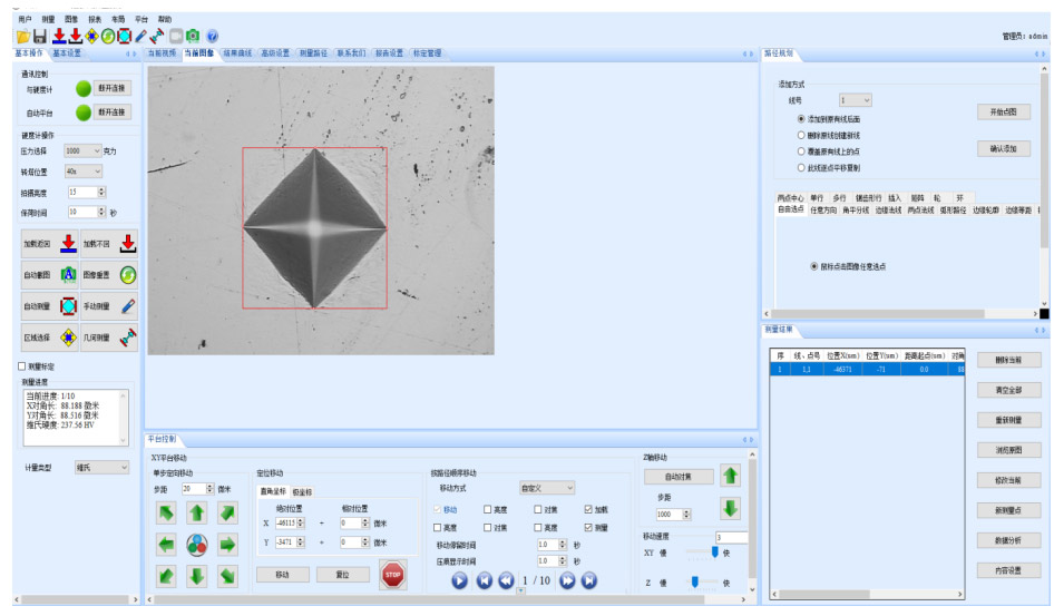
(Operation Interface Image)
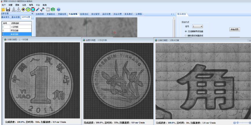
5.1 Panorama Stitching
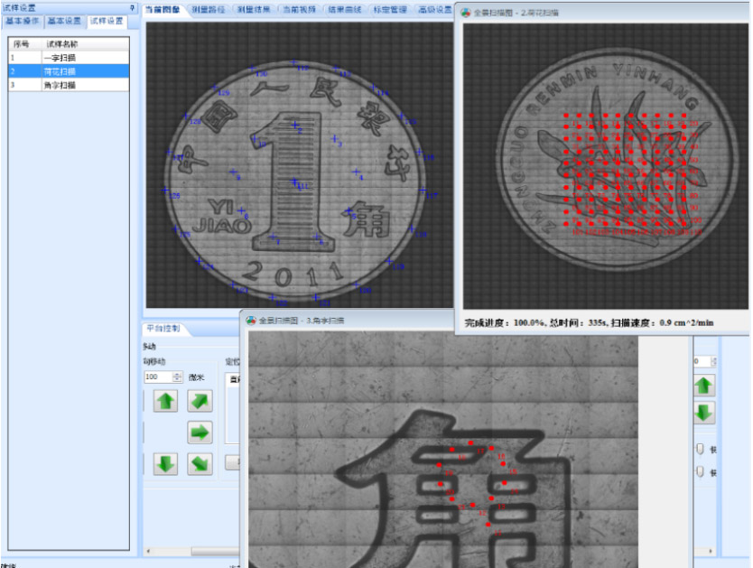
Using the "Panorama Stitching" function, the following panoramic image is obtained. You can also plan any path on this image.
Objective lens: 10X, Numerical Aperture: 0.25, Scanning speed: ~ 0.9 cm^2/min.
5.2 Panorama Stitching
With the 'Multiple Sample Panorama Stitching' feature, you can scan and stitch multiple samples at once to get several panorama images. You can also plan any path on the panorama images.
5.3 Freely Setting the Scan Area
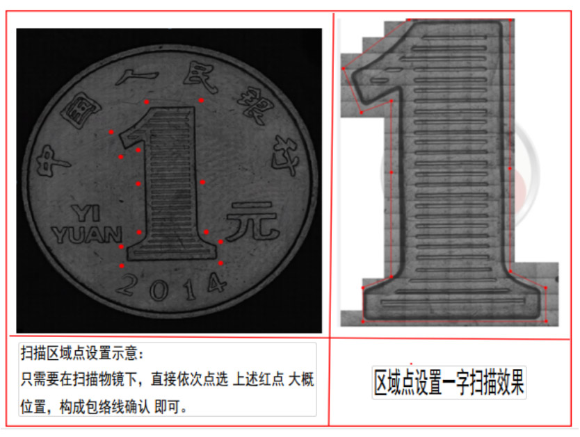
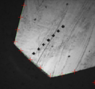
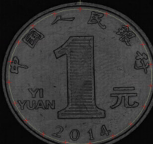
The feature of freely setting the scan area allows you to define the scan region according to the shape of irregular samples. This reduces the scanning range, saves scanning time, and improves work efficiency for customers.
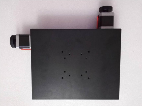
5.4 High-speed, high-precision automatic platform and high-precision Z-axis control system
5.5路径规划
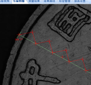
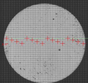
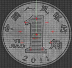
Precise planning of 17 path modes is realized by mouse clicking on the specimen image.
| Path Mode | Core Function Description |
|---|---|
| Free Point Selection | Click any position on the image to set measuring points. |
| Arbitrary Straight Line | Select a starting point to generate straight lines in any direction. |
| Edge Normal Line | Click near specimen edges to automatically generate normal lines. |
| Dual-Point Edge Normal Line | Select two endpoints on an edge to generate the central normal line. |
| Angle Bisector | Define an angle with three points and generate its bisector. |
| Arc Path | Set circle center and radius via two points to generate clockwise arc paths. |
| Edge Contour Tracing | Click beside edges to automatically trace along specimen outlines. |
| Offset Parallel Edge | Input offset distance to generate equidistant lines parallel to edges. |
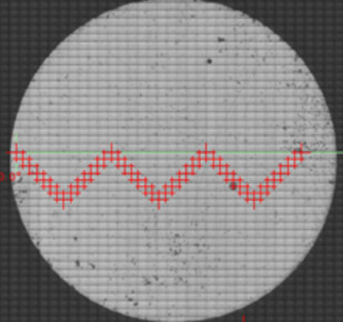
| Sawtooth Wave Path | Quantitatively adjustable cycle length, tooth height and tooth symmetry. |
| Midpoint of Two Points | Select two random points to calculate their central coordinate. |
| Path Mode | Core Function Description |
|---|---|
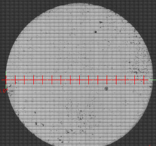
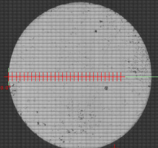
| Single Row Scan | Generate straight lines in any direction with variable spacing between measuring points. |
| Multi-Row Scan | Generate measuring points arranged in multiple parallel rows. |
| Multi-Row Sawtooth Scan | Sawtooth-shaped multi-row measuring path array. |
| Interpolated Points | Insert measuring points with fixed quantity or fixed spacing between two endpoints. |
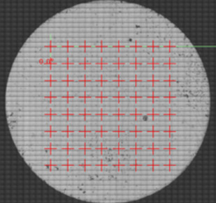
| Matrix Array Points | Generate measuring points arranged in rectangular matrix layout. |
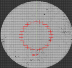
| Wheel-Shaped Points | Radial wheel distribution of measuring points. |
| Annular Ring Points | Concentric circular ring distribution of measuring points. |
| Edge Contour | Edge Equidistance |
|
|
Sawtooth Waveform | Center of two points |
|
|
Line | Multiple lines |
|
|
Sawtooth | Interpolation |
|
|
Matrix | Wheel |
|
|
Ring | |
|
5.6 Indenter Offset Correction
Indenters inevitably produce slight positional offset during operation, causing indentations to deviate from the center of the field of view (even moving out of view). The software matched with motorized stages features Indenter Offset Correction, which automatically adjusts indent position and centers all indentations in the field of view.
5.7 Automatic Measurement
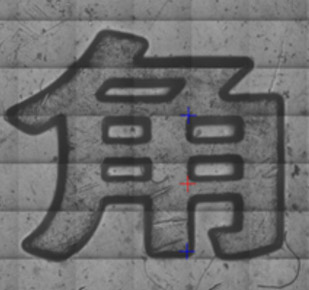
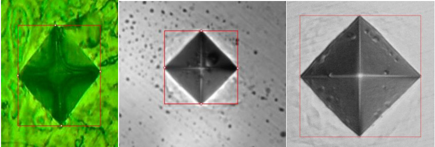
Adopted high-precision automatic recognition algorithm to accurately identify four vertices of Vickers indentations without manual line calibration. For rare indentations with hard-to-identify vertices, manual mouse calibration is available. The system supports automatic symmetry inspection of Vickers and Knoop indentations to ensure test results meet standard requirements.
5.8 Automatic Brightness Adjustment (Optional)
The optional automatic illumination system optimizes surface image brightness adaptively for all material types (steel, tool steel, cemented carbide, coatings, etc.). Optimized light contrast separates indentations from base material clearly, improving vertex recognition accuracy.
Note: This function requires corresponding hardware support.
5.9 Customizable Report Templates
All measured data can be stored and exported in Word, Excel and other common formats.
Users may customize report templates with self-defined logos, report contents and data sequence.
6.0 Early Test Termination (Optional)
For Case Hardness Depth (CHD) testing, users can set termination thresholds to stop the test process automatically once preset conditions are satisfied, saving testing time after reaching the limit of hardened layer depth.
6.1 3D Plane Hardness Distribution Diagram (Optional)
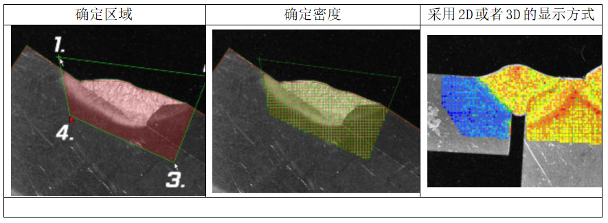
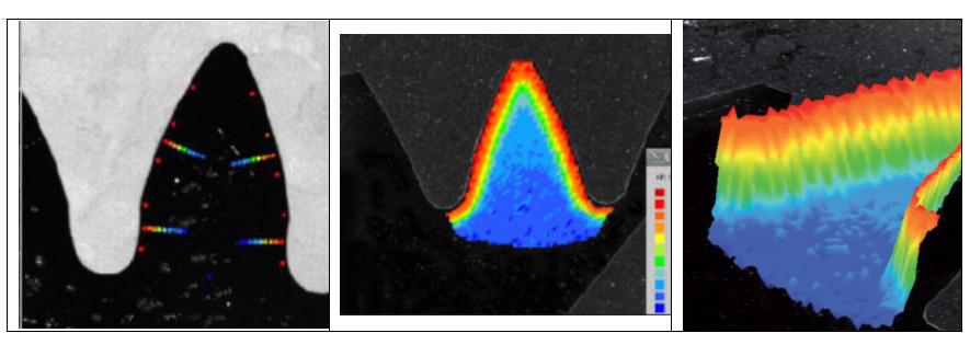
The 3D Plane Hardness Distribution function serves as an effective analytical tool for evaluating surface hardness distribution of heat-treated parts, widely applied in material research, welding quality inspection and component failure analysis.
| Item | Parameter | Remarks |
|---|---|---|
| Objective & Indenter Switching | Automatic switching | — |
| Turret Drive Mode | Copper gear transmission driven by stepping motor | — |
| Test Force (kgf) | 10gf, 25gf, 50gf, 100gf, 200gf, 300gf, 500gf, 1000gf | — |
| Test Force (N) | 0.098N, 0.246N, 0.49N, 0.98N, 1.96N, 2.94N, 4.90N, 9.80N | — |
| Loading Mode | Fully automatic program-controlled loading, dwell and unloading | — |
| Hardness Measuring Range | 5 HV – over 3000 HV | — |
| Eyepiece | 10× Digital Micrometer Eyepiece | — |
| Objectives | 10×, 40× | Two pieces standard |
| Total Magnification | 100×, 400× | Up to 1600× with computer |
| Minimum Resolution | 0.1 μm | — |
| Maximum Measuring Range | 200 μm | — |
| X-Y Motorized Stage | Stage dimension: approx. 140×180 mm; Max travel range: 50×50 mm | Custom travel available on request |
| Reading Method | Indentation image display & automatic measurement via computer | — |
| Max Specimen Height | 90 mm | — |
| Distance from Indenter Center to Machine Wall | 100 mm | — |
| Applicable Standards | GB/T 4340, ISO 6507, ASTM E384, JIS B7734 | International & domestic standards |
| Power Supply | 220 VAC, 50/60 Hz | — |
| Overall Dimension | Host: 480×325×545 mm; Outer packing case: 600×360×800 mm | L×W×H |
| Weight | Net weight: 31 kg; Gross weight: 44 kg | — |
| No. | Item | Quantity |
|---|---|---|
| 1 | Main tester unit | 1 set |
| 2 | 10× digital micrometer eyepiece | 1 piece |
| 3 | Coordinate measuring stage | 1 unit |
| 4 | Objective lens (10× & 40×) | 2 pieces |
| 5 | Vickers indenter | 1 piece |
| 6 | Mini spirit level | 1 piece |
| 7 | Standard hardness test blocks | 2 pieces |
| 8 | Power cord & auxiliary tool kit | 1 set |
| 9 | Spare light bulb | 1 piece |
| 10 | Motorized stage control box | 1 unit |
| 11 | CCD image processing system | 1 set |
| 12 | Branded industrial computer | 1 unit |
After-Sales Service, Quality Warranty & Technical Training
We take full quality responsibility for the complete set of supplied equipment.
One-year Three Guarantees (repair, replacement, refund) service against manufacturing defects counting from the on-site acceptance date at the buyer’s facility. Charges will apply for damaged components caused by non-manufacturing faults.
After the Three Guarantees warranty expires, paid maintenance service is available, covering spare part fees and engineer travel expenses.
For any equipment malfunction encountered by the buyer, contact our supplier at any time. We will reply within 24 hours; on-site engineer service will be arranged if on-site troubleshooting is required.
Free lifetime software upgrade service is provided.
Training: The supplier provides professional technical training for all the buyer’s operators.
The supplier offers full technical support during equipment operation upon the buyer’s request, including partial structural optimization, custom fixture design & fabrication, software function modification and other technical assistance.